


The following study was conducted by J.P. Bourcier after reading the book *Les clés de Vézelay*. The aim is to verify the plausibility of the proposed designs. Contrary to the sequence presented in the book, which derives the Gothic crossing from the pre-existing Romanesque nave, Mr. Bourcier carries out this construction in reverse, that is, from the crossing toward the nave. This approach allows us to reverse the direction of the geometric progressions and thus highlight any discrepancies.
For those who haven’t read the book, I must provide an explanation, without which the following exercise would remain unclear. The nave of Vézelay was built well before the transept crossing. It consists of 10 bays geometrically formed by equilateral triangles arranged head-to-tail.

The crossing, on the other hand, consists of two squares joined to two equilateral triangles. Indeed, in Gothic buildings, the crossing frequently takes the form of an equilateral triangle, whereas Romanesque crossings favor a square shape. Given that these two architectural styles coexist in the basilica, it becomes clear that the upper part of the Table (based on triangles) was designed to govern the Gothic structure as a whole, while the lower part (based on squares) was intended to accommodate the Romanesque nave.
Thus, the red segment you can see on the right-hand panel allows for the proportions of the nave bays to be taken into account. The length it defines is exactly the same as the sides of the triangles in the bays—that is, their respective widths. Thanks to this extraordinary geometric property, the architect of Vézelay succeeded in integrating the rhythm of the Romanesque nave into his design (see the Vézelay Tables system).
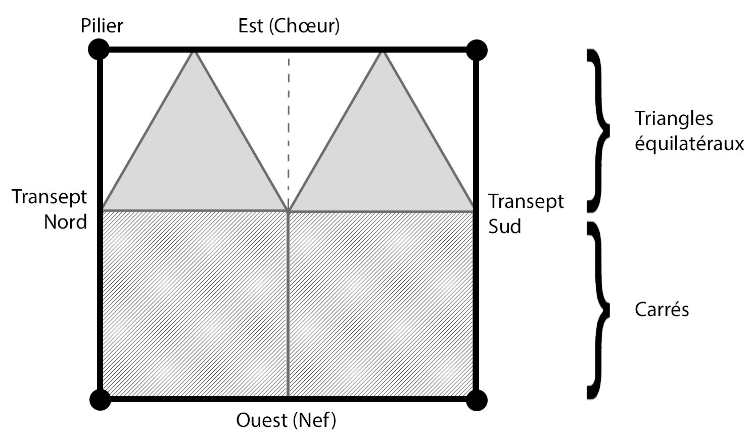
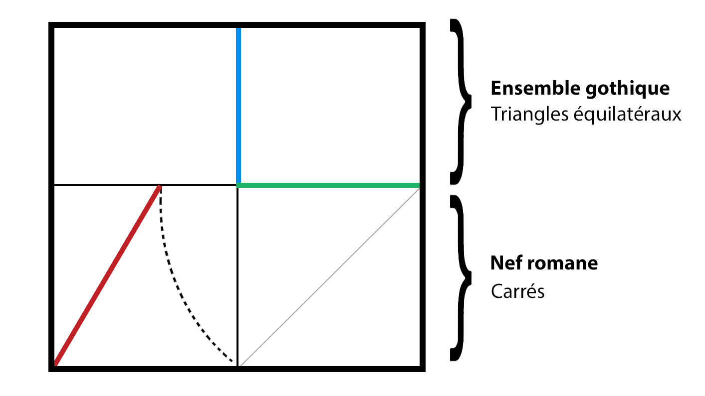
Plan of the basilica based on *Les clés de Vézelay*.
Jean Pierre Bourcier - Budapest, July 5, 2019
Since time immemorial, every sketch begins in the same way. A square line must be drawn to define two reference axes. So let’s assume that the square line 11–22 with center O has been drawn. On 11, the ½ width of the bay is marked on either side of O as OA and OB; a circle with radius OA is drawn; it intersects 22 at N. The intersection of two circular arcs with radius OA and centers A and N, and the intersection of two circular arcs with radius OA and centers B and N, define points C and D.
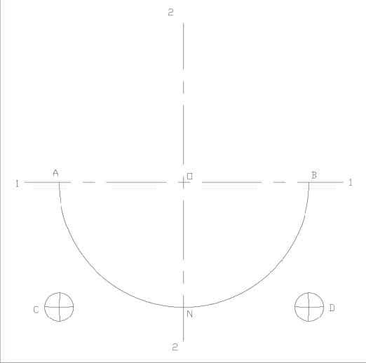
The intersection of two circular arcs of radius OA with centers A and O, as well as the intersection of two circular arcs of the same radius with centers O and B, define points E and F.

The table can then be drawn.

The arc with center B and radius BG is drawn; it intersects 11 at G1. The segment CG1 is drawn; it defines the width of the nave’s span.

The arc with center C and radius CG1 is drawn; it intersects axis 22 at G3 and the extension of AC at G2.

The triangle CG3G2 isis not equilateral; the perpendicular dropped from G3 to CG2 does not pass through the midpoint M of CG2. The positional deviation of the apex for a bay width of 10 m is 31 mm along axis 22, which is completely negligible compared to the dimensions of the building and the stakeout tools used.

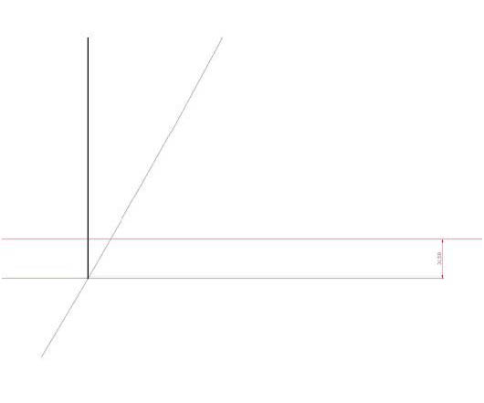
This deviation is comparable to that found in the layout of the choir’s polygon; here, the focus is not on the mathematical accuracy of the layout, but on its simplicity of execution, as the deviation is perceptible only to those in the know.
The extension of segment AH to AH1 and H1H2, along with the symmetrical layout relative to 22, allows for the definition of the second and third enclosures along direction 11.
Extending segment JK to JK1 and K1K2, along with drawing a line symmetrical to 11, allows us to define the second and third enclosures along direction 22.

From this layout, we can then draw the bays of the nave and the choir. At bay n, we apply Villard’s routine, which allows us to completely draw the choir.

This results in the following layout:

All that remains is to draw the narthex, following the layout in Figure 5. This presents an ambiguity, since the length of the rectangle differs from the length of the rectangle in Figure 6, which represents the bay width; according to the given plan of the basilica, the widths of the narthex and nave bays are identical. Furthermore, it is specified that the architect works from the opposite side of the nave aisle to make his markings. This results in a narthex bay width that is slightly greater than the nave bay width, which appears to be confirmed by the plan.

All of these drawings are perfectly realistic, as they use simple geometric shapes—squares and triangles—that are easy to draw. The compass is set to three different angles, and only two angles are used—45° and 60° (or 30°, its complement)—which are easy to memorize.
It goes without saying that, up until the end of the 19th century, many construction lines were part of routines that were memorized and could be applied without requiring knowledge of their proofs—all so that workers could use them easily. For example, the routines in the booklet on wood carpentry.
And what about the golden ratio in all of this? The best thing to do is send a text message to Nicolas Flamel, with a copy to the Count of St-Germain, to get the answer.
Les cathédrales retracées

The Keys of Vézelay

Comments

David Orbach (Architecte - Ingénieur structure - Enseignant à l’Université Populaire de Caen de Michel Onfray)

Jean-Michel Mathonière - Directeur éditorial chez Éditions Dervy - Historien des compagnonnages

Cathédraloscope

Site : lescathedrales.wordpress.com

Jean-Pierre Bourcier - Spécialiste du trait

Olivier Petit - Médiéviste

Jean-François Lecompte - écrivain

Luciano Xavier - Maquettiste en cathédrales gothiques

Arcana Les Mystères du Monde - Youtubeur (Chaine Arcana)

troph38

Jean-François Lecompte - écrivain
John Brown

Armand Priest (ESTP) - Commentaire Facebook

Anthony CRESTIN - La géométrie et le mythe

Joël Supéry

Asso Fermat-Science

M. Moldovan

Catherine Leschenne


Dominique Gury